
A facility manager will often think a fire hose reel installation is straightforward. The reel arrives, a plumber connects the pipework, the drum is fixed to a wall, and the job is signed off. On a Queensland retrofit, that assumption can unravel before the first fixing is installed.
The work is deciding whether the selected wall can carry the loaded unit, whether the hose can cover the storey without crossing barriers, whether the reel remains visible and accessible, and whether the water supply will perform during commissioning and later servicing. Under AS 2441, the installation must satisfy dimensional, access and placement requirements, while AS 1851 makes ongoing inspection and testing part of the asset's compliance lifecycle.
Table of Contents
- When a Fire Hose Reel Install Becomes a Compliance Headache
- Site Assessment Before You Drill a Single Hole
- Choosing the Right Reel Type and Mounting Method
- Mounting Heights, Clear Zones and the Wall Itself
- Water Supply, Pressure and Flow on Test Day
- Commissioning, AS 1851 Servicing and Your QLD Logbook
- After the Install, What Keeps It Compliant
When a Fire Hose Reel Install Becomes a Compliance Headache
A Brisbane warehouse fitout demonstrated how quickly a routine hose reel order can become a coordination problem. The facility manager had ordered three reels, but the proposed layout created several compliance risks. The nominated Hebel wall lacked the structural backing for the selected fixings, the nearest exit placed the hose route beyond the practical 40 m reach envelope, and a roller door track occupied the operating area for one reel.
Changing the screw would not resolve those conflicts. The wall construction, exit route, roller door movement and hydraulic layout needed to be assessed as one installation.
Practical rule: A reel location can look suitable on a plan, then fail when the hose is pulled out, the cabinet opens and the user needs to stand in front of it.
Hose length is only one part of the Australian installation check. AS 2441 works from a 36 m hose plus an assumed 4 m stream, giving a practical 40 m reach envelope for layout purposes. The reel must also remain visible and accessible, generally within 4 m of an exit. Its centreline is set at about 1400 to 2400 mm above finished floor level, with the stop valve around 900 to 1100 mm high and an unobstructed 1000 mm clear zone in front. These requirements are outlined in Australian AS 2441 installation guidance.
The mounting decision also affects the compliance lifecycle. A weak partition can require backing, a recessed unit can create clearance problems, and a cabinet can obstruct use if its door or hose path conflicts with nearby equipment. Those decisions affect inspection and testing under AS 1851, not just the day the reel is installed.
Queensland buildings must be checked against the National Construction Code and the approved fire-safety design. The NCC states that fire hose reels serve the storey where they are installed, subject to a narrow exception for certain sole-occupancy units of no more than two storeys in specified building classes. The storey-by-storey limitation appears in NCC fire-fighting equipment provisions.
A compliant installation starts with coordinated decisions about structure, egress, access, hose travel, water supply and the records required after handover.
Site Assessment Before You Drill a Single Hole
Treat the site assessment as a compulsory survey, not a paperwork exercise. Walk the entire protected floor with the plan in hand and identify the furthest point the hose and nozzle must reach. Under the practical AS 2441 layout rule, check the 36 m hose and assumed 4 m stream together, while also confirming that the hose path won't be blocked by partitions, machinery, stock or fixed barriers. Fire-block planning guidance can help organise this information before the installation layout is finalised.
Measure the physical constraints
Start at the proposed reel and measure toward the furthest relevant part of the floor, not just the centre of the room. Then record:
- Wall construction: Identify concrete, reinforced masonry, steel stud, timber stud, Hebel or another lightweight partition. Note stud spacing and whether backing is already installed.
- Exit relationship: Confirm the reel is generally within 4 m of an exit, and make sure its position doesn't narrow the egress path or interfere with an exit door.
- Ceiling and movement: Check ceiling height, beams, ductwork and the arc of any swing arm. A reel can meet reach distance and still be unusable if the arm strikes a service or the door cannot open.
- Water connection: Locate the existing hydrant or fire-service feed, the nearest isolation point and the proposed test valve position. Confirm whether the building supply can support another reel without compromising other fire services.
- Finished floor level: Measure from the actual finished floor, including tiles, coatings or raised platforms. Rough slab measurements can leave the valve or operating parts at the wrong height after the fitout is complete.
Photograph the proposed mounting wall from several angles, including nearby doors, racks, switchboards and plant. Take separate images of the proposed water connection, test valve location, ceiling obstructions and any fire-rated wall or lining that may be affected by drilling.
Record what the certifier will need
Keep the survey photographs with the marked-up plan and installation notes. A clear compliance file should show why the location was selected, how the coverage was checked, what wall support was available and where the supply was taken from.
Queensland budget accommodation guidance also requires the fully extended hose to avoid partitions and other physical barriers so it can reach every part of the storey floor. Where a floor area exceeds 500 m², that guidance calls for a fire hose reel system installed to the Australian Standard current at the time of installation. The relevant Queensland material is available in fire safety guidance for budget accommodation buildings.
Choosing the Right Reel Type and Mounting Method
The right configuration depends on the building, the wall and the way people will reach the reel under pressure. A fixed wall-mounted unit may suit a corridor, while an open warehouse may need a swing-arm arrangement to place the hose around racking or plant. A recessed cabinet can look tidy in a finished tenancy, but it can create structural and fire-rating problems that a surface-mounted unit avoids.
Reel configuration comparison
| Reel Configuration | Best Fit | Watch Out |
|---|---|---|
| Fixed wall-mounted reel | Offices, corridors, smaller commercial tenancies and straightforward plant-room walls | The hose path can be restricted by shelving, doors or equipment positioned beside the reel |
| Swing-arm reel | Open warehouses and areas where the hose needs to move around the mounting point | Requires solid structural backing and enough space for the arm and hose to swing without striking obstructions |
| Surface-mounted cabinet | Retrofit work, concrete walls, plant rooms and locations where wall depth is limited | More visible than a recessed cabinet and can project into circulation space |
| Recessed cabinet | New commercial fitouts where appearance and protected presentation matter | Needs adequate wall depth, coordinated framing and careful treatment of fire-rated linings |
| Open drum | Low-obstruction areas where the reel is immediately visible and easy to operate | More exposed to impact, dust and accidental interference |
| Glazed-door cabinet | Retail, healthcare, offices and shared facilities where protection and visibility are both important | The door, signage and opening arc must remain clear and usable |
For an open warehouse, a swing arm often provides better practical coverage, but only if the wall or supporting frame can take the working load. A surface-mounted cabinet is usually the safer retrofit choice where the existing partition depth is unknown. In a new Class 2 or Class 3 fitout, a recessed cabinet may give the cleanest result, provided the framing, lining and fire-rating details are resolved before the wall is closed.
Finish selection should follow the environment. Galvanised components suit many dry plant rooms and general commercial areas. Stainless steel is a stronger choice where moisture, washdown or coastal air is a concern. Red powdercoat gives a familiar fire-equipment finish and works well where visibility is important, but the coating still needs protection from impact and harsh chemicals.
The hardware should be specified to the Australian market. AS/NZS 1221:1997 covers the design, construction and performance of fixed and swing-arm fire hose reels intended for use by one operator, as listed by Standards Australia. Don't rely on an overseas product description or international class label without confirming the Australian standard and the installation requirements.
Mounting Heights, Clear Zones and the Wall Itself
A hose reel can meet its product specification and still fail on site if the wall, clearance or access position is wrong. The wall forms part of the fire-protection system. If the backing cannot resist the loaded reel, hose pull or swing-arm movement, the installation becomes unsafe during use and difficult to maintain under the AS 1851 compliance cycle.
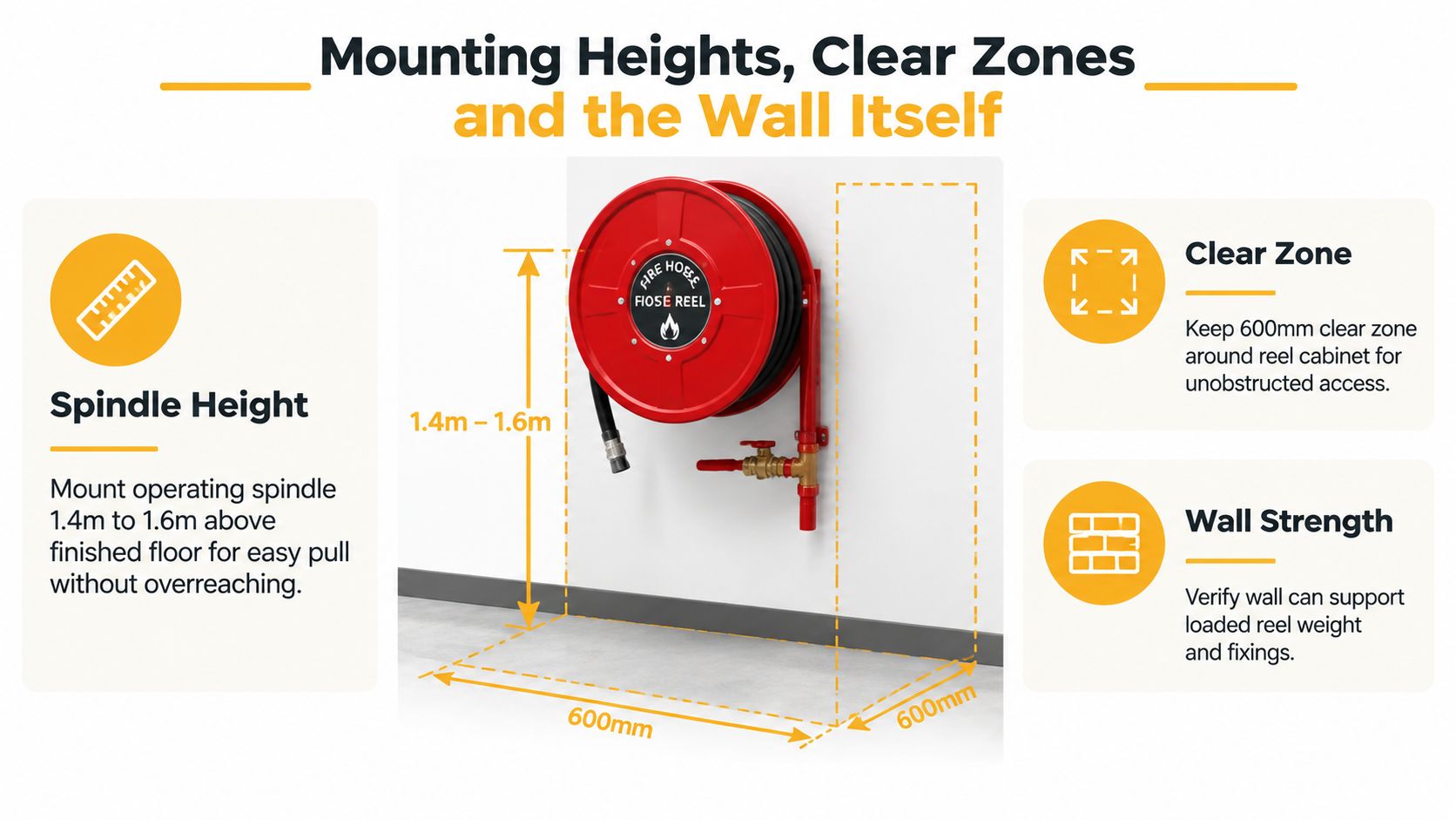
Set out the operating spindle between 1.4 m and 1.6 m above finished floor level so the reel is practical to operate. Check the full AS 2441 dimensional layout as well. The reel centreline must be about 1400 to 2400 mm above finished floor level, the stop valve about 900 to 1100 mm high, and the reel front must retain an unobstructed 1000 mm clear zone. These dimensions are shown in the installation reference below.
Match the fixing to the wall
Concrete and reinforced masonry can generally take engineered anchors selected for the reel load and the actual substrate. A stud wall needs correctly positioned backing, such as 18 mm plywood or a steel spreader plate behind the plaster. Fixings placed only into plasterboard are not an adequate support method. Lightweight partitions may require a freestanding steel frame transferring the load into the floor or another suitable structural member.
Fire-rated walls require coordination before drilling. Penetrations, sleeves, backing and fire stopping can affect the tested wall system, so confirm the proposed detail with the building certifier or the person responsible for that construction. A recessed cabinet is not a compliant outcome if the surrounding fire-rated wall has been compromised.
Complete the installation in a controlled sequence
- Set out the reel and cabinet. Check the spindle, valve, signage and operating position against the finished floor, nearby exits and doors.
- Prove the clear zone. Account for door swings, storage racks, switchboards, handrails and the user standing at the reel. Retain the specified 1000 mm front clearance, then check the extra movement required by a cabinet door or swing arm.
- Install structural backing and fixings. Select the fixing method from the actual wall construction, not an outdated tenancy drawing.
- Connect the water supply. Provide isolation and test arrangements that allow servicing without uncontrolled discharge or blocked access.
- Fit the valve, hose and nozzle. Confirm that the nozzle comes away easily, the hose unwinds without snagging and the guide roller or arm travels through its complete range.
- Install signage after movement is proven. The sign must identify the reel without obstructing the cabinet door, swing arc or nozzle.
Uneven floors cause avoidable retrofit problems. A recessed cabinet may appear level at its top while the nozzle sits awkwardly because the floor falls away. Test the actual operating position and hose movement, not just the cabinet face.
Demonstrate the finished operation before closing the wall or handing the area back. The following video gives a practical visual reference for reel operation and installation considerations.
Water Supply, Pressure and Flow on Test Day
Hydraulic performance must be proven at the reel, not assumed from the building's general water pressure. The figures often used in Australian installation specifications are 0.33 L/min per nozzle, 220 kPa running pressure at the nozzle, and 200 kPa minimum static pressure at the valve inlet, with the rated hose length commonly specified as 30 m. Those acceptance values are set out in the AS 2441 pressure and flow reference.
| Parameter | Acceptance Value | Test Method |
|---|---|---|
| Nozzle flow | 0.33 L/min per nozzle | Discharge through the fully opened nozzle and measure the flow at the operating end |
| Running nozzle pressure | 220 kPa | Read the gauge while water is flowing at the nozzle |
| Static valve inlet pressure | 200 kPa minimum | Record pressure at the valve inlet before opening the reel |
| Hose basis | 30 m rated hose length, where specified for the reel | Confirm the installed reel and hose match the approved product and design |
Identify the supply before connecting
A dedicated 25 mm feed from the building main may be appropriate for a straightforward installation, but the connection still needs hydraulic confirmation. A metered fire-service connection or a tie-in to a hydrant ring main can change the pressure available at the reel and may require coordination with the building's fire-service design and local authority requirements.
High-rise Queensland sites need particular attention to zoning, booster arrangements and available pressure at upper levels. Where the building design requires a break tank and pump set, the hose reel connection must be coordinated with that system rather than treated as a domestic plumbing extension.
Shared domestic services are a frequent source of trouble. A supply can appear adequate while other fixtures are idle, then fall away when the building operates normally. Missing non-return valves on potable-water tie-ins can also create a service and cross-connection problem. Undersized feed pipework, long runs, excessive bends and poorly selected valves all show up at test time.
Test the reel as it will be used
Open the valve fully and run the hose to the test position. Read the pitot gauge at the end of the hose, record the static pressure before discharge and then record the residual or running pressure while water is flowing. Confirm the discharge pattern is stable and that the stream reaches the coverage area used in the layout check.
The installer should log the test location, instrument readings, hose identification and any temporary test arrangement. If the result misses the required performance, don't hide the problem by throttling the nozzle or recording a pressure from a more convenient point. Trace the restriction back through the feed, valve, backflow protection and building supply.
A reel that passes a visual inspection but fails its flow test isn't ready for handover. The test result is the evidence that the installation can deliver its intended protection under operating conditions.
Commissioning, AS 1851 Servicing and Your QLD Logbook
Commissioning turns installed hardware into a managed fire-safety asset. The handover pack should connect the physical reel to the building's records, its location and its future inspection program.
Complete the handover record
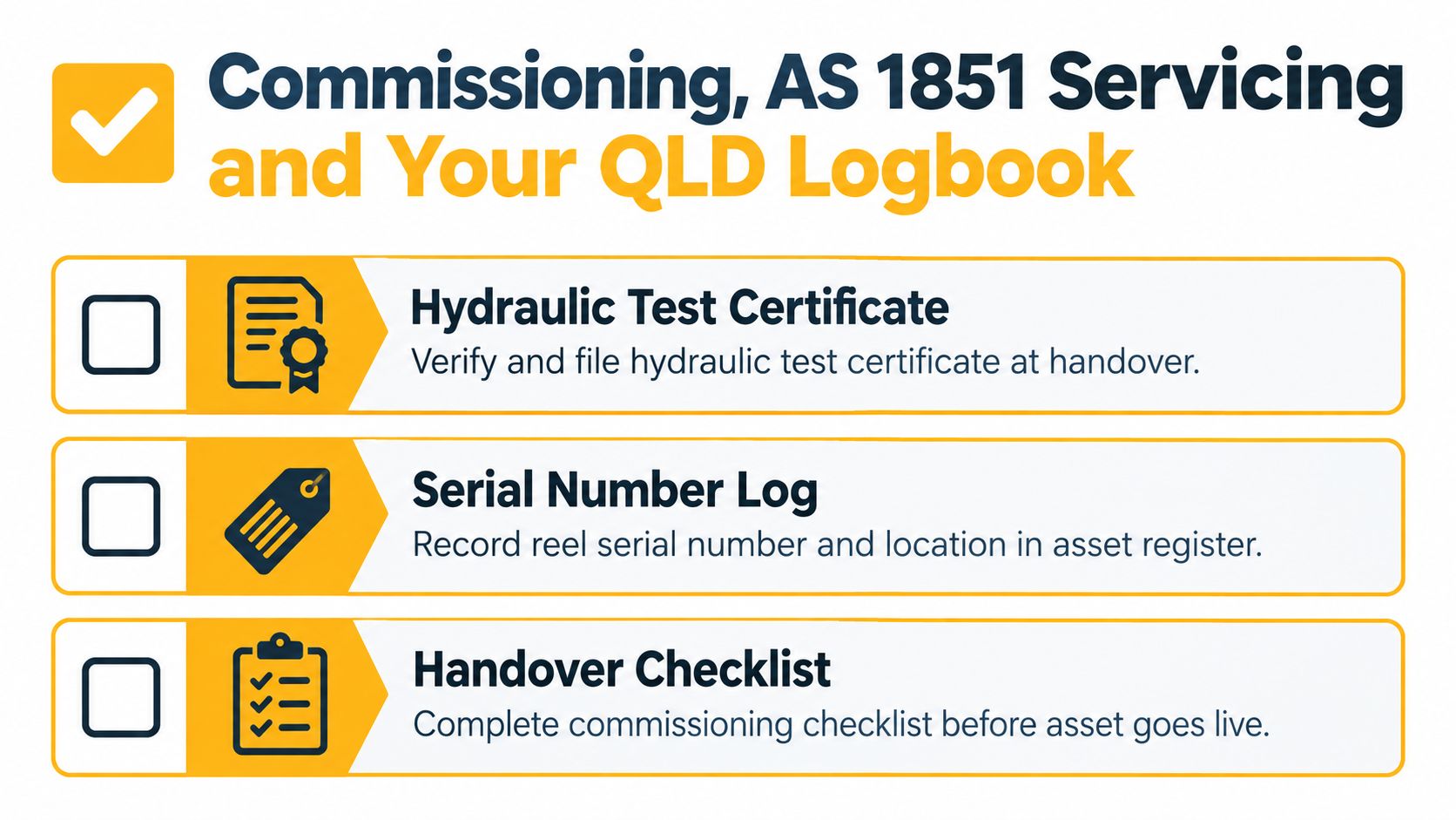
At handover, verify and file the hydraulic test certificate, record the reel serial number and location against the asset register, and confirm the reel signage is installed and visible. Record the static pressure reading alongside the running test results so future technicians can compare performance rather than starting with an empty baseline.
The asset register should identify the building, storey, room or zone, reel configuration, cabinet location and relevant isolation point. If the reel is hidden behind a tenancy fitout or identified only by an incomplete floor-plan mark-up, the next service technician may waste time locating the asset or miss it altogether.
Keep the following with the Queensland fire-safety records:
- Hydraulic evidence: File the commissioning and pressure test certificate.
- Asset identity: Record the serial number, location and installation date.
- Access confirmation: Note that the reel, nozzle, valve and signage were accessible at handover.
- Defect status: List unresolved items, the responsible party and the close-out evidence.
The lifecycle distinction matters. AS 2441 governs installation, while AS 1851 governs routine service activities. Current Australian guidance separates those responsibilities, so an installation certificate doesn't replace recurring inspection, flow testing and defect management. The relevant standards context is available through Australian Standards information for fire hose reels.
Build the service rhythm into the logbook
Queensland compliance material identifies six-monthly checks and an annual nozzle flow and pressure check for hose reels, with hoses replaced where their condition doesn't meet the required criteria. The service provider should inspect hose condition, nozzle operation, valve leak-tightness and guide roller function, then record the outcome in the site logbook.
A Queensland auditor or building certifier will generally want to see organised records rather than a loose service sticker. Keep the AFSS logbook entries, annual flow-test certificates from an appropriately licensed QBCC fire licensee and evidence that defects have been rectified and closed out within the required timeframe.
For practical service planning, see fire hose reel maintenance guidance. Add photographs when they clarify the condition of a cabinet, hose, valve or obstruction. A defect tag should state what failed, what action is required and whether the reel remains available for use.
After the Install, What Keeps It Compliant
The installation is only the opening stage of the asset's working life. A facility manager needs a repeatable process that catches access problems, deterioration and hydraulic changes before an auditor or emergency exposes them.
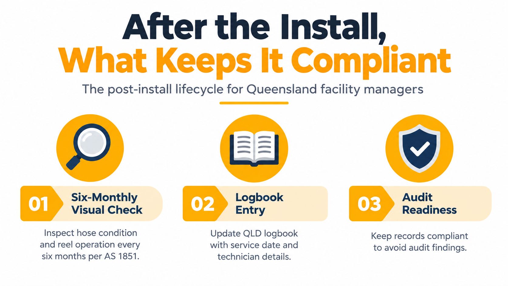
The six-monthly visual check under AS 1851 should cover hose condition, nozzle operation, valve isolation, signage legibility and drum rotation. The annual flow test should record the operating pressure and discharge result against the original commissioning baseline, making it easier to identify a gradual loss of performance.
Watch for retrofit defects that return
Some faults are hidden until the cabinet is opened or the hose is operated:
- Corroded copper stubs: Moisture and incompatible conditions can weaken the connection behind the cabinet.
- Seized drum bearings: Coastal exposure, dust and infrequent operation can make the reel difficult to rotate.
- Perished swing-arm O-rings: A leaking pivot can affect operation and leave water damage around the mounting point.
- Painted-shut cabinets: Repainting over doors, hinges or glazing can prevent immediate access and obscure the equipment.
- Blocked operating zones: New shelving, signage, stock or switchboards can gradually consume the clear area established at installation.
A hose-only replacement makes sense when the drum, valve, guide roller and bearings remain serviceable and the defect is confined to the hose. A full reel replacement is more appropriate when the drum, valve, bearing or swing-arm assembly has also reached the end of its serviceable life, or when compatible replacement parts can't restore reliable operation.
Keep this audit checklist with the asset file
- Signage: Confirm the reel sign is visible, legible and not blocked by a cabinet door, stock or new fitout work.
- Access: Check the front operating zone, hose path, nozzle and valve.
- Logbook: Record the service date, technician details, findings and any defect close-out.
- Photo evidence: Attach images where they show access, condition, repairs or the completed rectification.
- Hydraulic record: Keep the annual flow and pressure results comparable with commissioning data.
- Next test date: Record the next six-monthly inspection and annual flow test dates in the Essential Safety Measures file.
- Hose condition: Replace the hose when it fails condition criteria rather than waiting for a leak or operational failure.
Celtic Fire & Security supplies, installs, tests and maintains fire hose reels, including pressure and flow testing, documentation and scheduled compliance maintenance across North Brisbane, Moreton Bay, the Sunshine Coast, Somerset and Ipswich. To plan a compliant installation or arrange servicing for an existing asset, visit Celtic Fire & Security and request an assessment of the reel locations, wall conditions, water supply and Queensland logbook requirements.
No responses yet