
A property manager has a fire safety audit approaching, but the hydrant system file is incomplete. The previous contractor's flow certificate is missing, the booster records are unclear, and the local water authority hasn't confirmed whether the available street supply still matches the original design assumptions. The building may look unchanged, yet the evidence needed to prove that its fire hydrant systems will work can be difficult to assemble.
That situation is common on commercial sites. A hydrant system isn't just a row of valves and cabinets. It's a coordinated water supply, distribution network, booster arrangement, access plan, testing facility and maintenance record. The practical benchmark is AS 2419.1:2021, supported by ongoing maintenance under AS 1851, Queensland building requirements and fire safety obligations. The following lifecycle approach helps facility managers understand what should happen from design and installation through to testing, fault diagnosis and audit preparation.
Table of Contents
- Why Commercial Fire Hydrant Systems Matter on Australian Sites
- How a Fire Hydrant System Actually Works
- Pumped Versus Un-Pumped Hydrant Systems
- Designing and Installing Hydrants for Testability
- Step-by-Step Hydrant Flow Testing Procedure
- When the Test Fails and It Is Not Your Fault
- Maintenance, Inspections, and AS 1851 Routines
- Putting It All Together for Compliance
Why Commercial Fire Hydrant Systems Matter on Australian Sites
A commercial hydrant system has two jobs. It must deliver usable water for firefighting, and it must allow responding crews to find, connect to and operate the equipment without wasting time. A system that technically exists but has blocked valves, poor signage, incomplete records or inadequate flow creates a serious operational problem.
In Australia, AS 2419.1:2021 is the key design and commissioning reference for fire hydrant systems. The current standard was approved on 20 August 2021 and later became the primary referenced document in NCC 2022, continuing a formal standard lineage from AS 2419-1980 through several revisions to the current edition. The Standards Australia reference for AS 2419.1:2021 provides the authoritative starting point for design and performance decisions.
Queensland guidance also treats AS 2419.1 as the minimum design and performance standard for installed reticulated fire hydrant systems. That matters for commercial owners because design compliance isn't finished when the pipework is installed. The owner must be able to demonstrate that the system remains accessible, testable and capable of meeting its intended performance.
The risks of a weak compliance trail
An auditor, certifier, insurer or fire authority may need to see more than a recent service sticker. The useful evidence usually includes:
- Current drawings: These should identify hydrants, booster assemblies, isolation valves, test points and pressure zones.
- Commissioning records: The original results should show how the installed system performed against its design criteria.
- Periodic test certificates: Results should identify the test location, readings, equipment used and any restrictions.
- Defect history: Repairs, valve replacements, access changes and network correspondence should remain attached to the site record.
- Access evidence: Hydrant doors, cabinets, booster connections and discharge routes must remain usable.
Blocked hydrants, undocumented flow tests or an unverified booster can delay approvals and create difficult questions during an insurance or regulatory review. The broader point is simple: the system protects people only when the hardware and the evidence are both maintained.
Practical rule: Treat every test result as part of the building's permanent fire safety history, not as a disposable form completed for one visit.
How a Fire Hydrant System Actually Works
Think of a hydrant system as the building's firefighting plumbing network. A domestic plumbing system brings water into a building and distributes it to outlets. A fire hydrant system does the same basic job, but it's engineered around high-volume firefighting demand, brigade access and predictable performance at the least favourable outlet.
The four main building blocks are:
- Water supply: This may be the town water main or a dedicated fire water storage tank. The supply provides the water that enters the private hydrant network.
- Ring main: A looped pipe network distributes water around the building or site. A ring can provide alternative flow paths, subject to the design and isolation arrangement.
- Booster arrangement: Where the available mains pressure or flow doesn't satisfy the design, a fire pump set increases pressure and supports delivery through the system.
- Hydrant outlets: Landing valves, pit hydrants or pillar hydrants provide connection points for fire hoses. The outlets use Australian fire brigade-compatible couplings and must remain accessible.
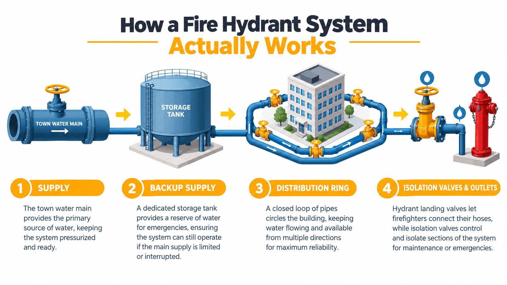
Under static conditions, the pipework remains charged with water and the system holds pressure. When a hydrant valve opens, water begins moving through the pipework. The pressure measured while water is flowing is called residual pressure, and it's the flowing condition that reveals whether the system can perform at the required outlet.
For Queensland Class 2 to 9 buildings with installed reticulated systems, the minimum required flow is 10 L/s at 200 kPa. AS 2419.1:2021 also requires at least 10 L/s from each required feed hydrant outlet, regardless of its location, as described in Queensland Fire and Emergency Services hydrant guidance. The critical test point is the most hydraulically disadvantaged hydrant, meaning the outlet where the system has the greatest hydraulic difficulty delivering the required result.
The booster cabinet normally includes suction and boost inlets. Fire crews can connect external pumps through these connections to support the building's water supply during an incident. That arrangement is why booster location, vehicle access, signage and unobstructed connections deserve the same attention as the internal pipework.
Pumped Versus Un-Pumped Hydrant Systems
Pumped and un-pumped systems aren't interchangeable options. The right arrangement depends on the water available at the property boundary, the building's hydraulic design and the performance that must be demonstrated at the required hydrants.
| Aspect | Un-Pumped System | Pumped System |
|---|---|---|
| Water source | Relies on town mains pressure and flow | Uses town mains, tank storage or both, with a fire pump set supporting delivery |
| Site suitability | Works where the water provider can demonstrate reliable supply performance | Suits sites where mains supply alone can't satisfy the design |
| Installation impact | Simpler pipework and fewer mechanical components | Requires pump equipment, controls, supporting services and suitable plant space |
| Maintenance profile | Fewer components, but strong dependence on external network conditions | More equipment to inspect, operate and document under the maintenance schedule |
| Main risk | A change in street supply can reduce system performance without any private-site alteration | Mechanical, electrical or fuel-related faults can affect availability if maintenance is neglected |
| Testing focus | Flow and residual pressure at the critical hydrant, with attention to network results | Pump operation, tank or mains supply, controls, pressure and flow at the critical hydrant |
An un-pumped system can be an efficient choice for a suitable commercial property. It avoids a fire pump room and reduces mechanical complexity, but the owner remains exposed to changes in the town network. A hydrant may pass one test and deliver a different result later because of external supply conditions, seasonal demand, network works or changes beyond the site boundary.
A pumped system brings greater independence, but it occupies space and needs supporting infrastructure. Designers must account for pump access, electrical supply, diesel fuel where applicable, ventilation, drainage, control equipment and safe discharge during testing. Those components also add service points that a technician must verify.
A cheaper installation isn't automatically the lower-risk installation. The useful comparison is the cost and effort required to prove reliable performance throughout the system's working life.
For either arrangement, the test certificate should identify what was tested and under what conditions. On an un-pumped site, a borderline result should trigger early communication with the water service provider rather than repeated private-system repairs without evidence.
Designing and Installing Hydrants for Testability
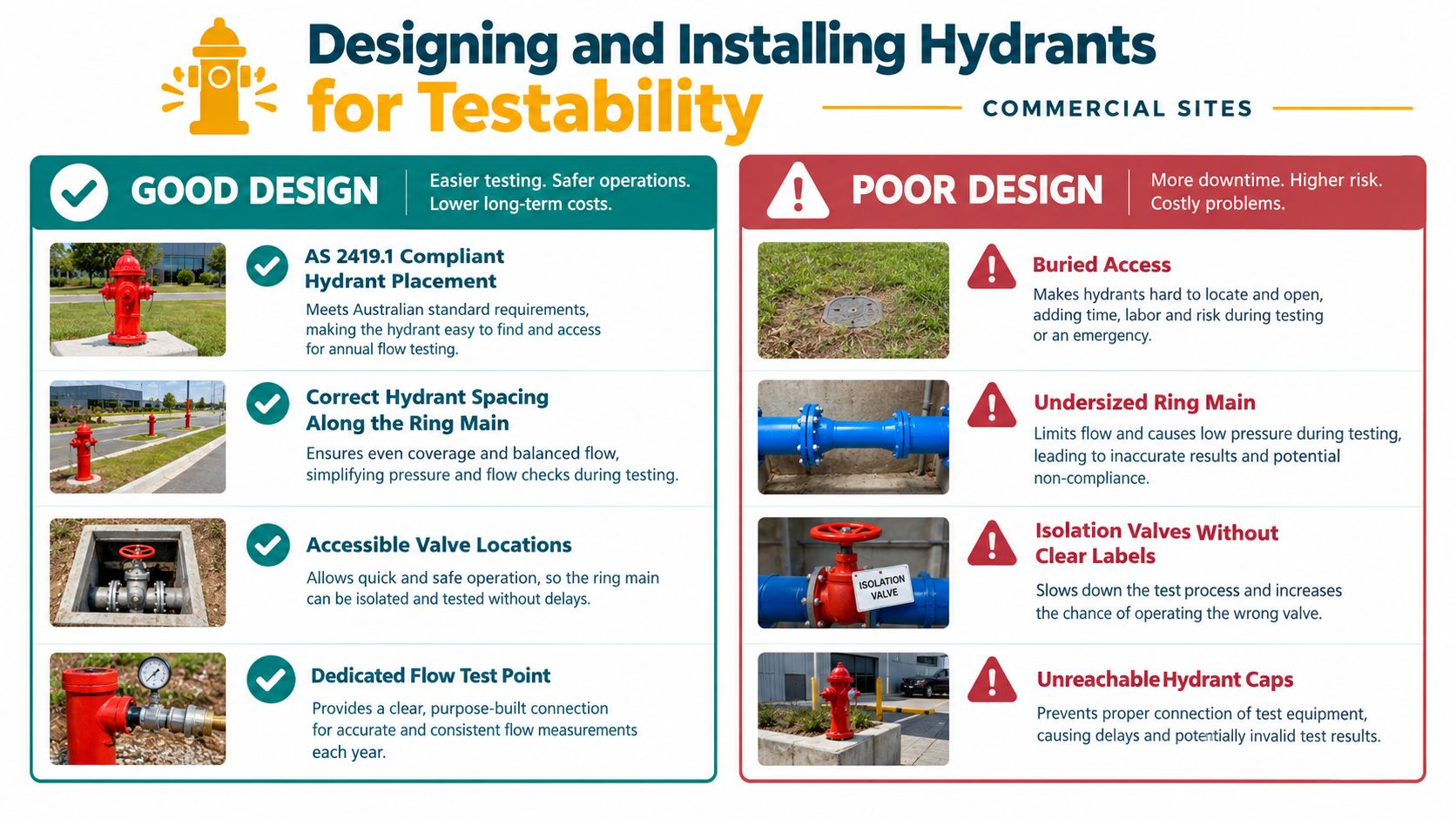
Good hydrant design makes future testing routine. Poor design turns every service visit into an investigation involving buried valves, inaccessible test points, unclear isolation arrangements and uncontrolled water discharge.
Start with the design drawings. Hydrant placement should follow AS 2419.1 and reflect the building's fire brigade access requirements. Queensland guidance links hydrant placement to roadways or access ways for material changes of use and reconfigured lots, so the site plan must be considered alongside the building layout, vehicle movements and brigade approach routes.
Layout decisions that affect service work
A technician will assess more than the location of the outlet itself:
- Access routes: Fire appliances and technicians need clear approaches to booster assemblies, pits, pillars and test facilities.
- Valve identification: Isolation valves should be accessible, labelled and shown consistently on the hydrant block plan.
- Ring main arrangement: Pipe routes should support the hydraulic design while avoiding unnecessary complications during isolation and fault finding.
- Test connections: Test inlets must allow the required outlets to flow without relying on improvised hoses or unsafe discharge points.
- Drainage: Flow water needs a controlled route. A test that floods a plant room or undermines paving isn't a practical test facility.
- Signage and protection: Cabinets, booster connections and hydrant locations need durable identification that remains visible after landscaping and site changes.
Queensland Fire and Emergency Services states that the number of test inlets should support the number of hydrants required to flow. Its example identifies two test inlets for a 20 L/s test flow, and it calls for a permanent test facility for each pressure zone and/or tower. Fixed drains must be sized and pressure-rated for the test conditions under applicable NCC and AS/NZS 3500 requirements, as explained in the Queensland guidance on fire hydrant test facilities.
The trade-off is often between a shorter pipe route and better long-term access. Moving a booster or test point to save construction space may make installation easier, but it can make later testing slower and more disruptive. For strata buildings, towers and sites with separate pressure zones, design-for-maintenance should be considered before concrete, landscaping and tenancy fit-outs conceal access points.
Keep the fire block plan information current after every valve, pipework or access change. A plan that reflects the original construction but not the current site is a liability during both testing and an emergency.
Step-by-Step Hydrant Flow Testing Procedure
A flow test should prove performance at the outlet most likely to struggle, rather than just produce a reassuring reading at the nearest hydrant. The test sequence needs to control the equipment, the measuring instruments, the discharge and the recordkeeping.
1. Confirm the system condition
Review the drawings and previous certificates before operating the system. Confirm whether the site is pumped or un-pumped, identify the pressure zones, check that the test facility can discharge safely and inspect the booster assembly for obvious damage or obstruction.
On a pumped system, confirm the pump controls and operating condition before flowing water. A pump that starts late, fails to maintain pressure or has an alarm condition should be investigated before relying on the flow result.
2. Find the critical hydrant
The most hydraulically disadvantaged hydrant is the outlet selected because it presents the greatest hydraulic challenge. It may be the most remote outlet, the highest outlet or the one identified by the approved hydraulic design. Don't assume the closest or most convenient hydrant is representative.
3. Fit suitable instruments
Use calibrated pressure gauges suitable for the test arrangement. Check the gauge connection, zero position, seals and condition before flowing. The static reading provides useful context, but the residual pressure under flow is the result that shows how the system behaves while water is being delivered.
4. Open the outlet in a controlled way
Open the pit, pillar or landing valve carefully and direct the discharge through the approved test facility. The flow measuring device should be correctly fitted, and the operator should watch for movement, leaks, hose reaction, drainage problems or pressure instability.
Queensland's periodic maintenance procedure requires the test at the most hydraulically disadvantaged hydrant, with a flow measuring device opened to 10 litres per second and residual pressure recorded from the flowing hydrant's gauge. The Queensland mandatory hydrant and sprinkler maintenance procedure sets out that measurement approach.
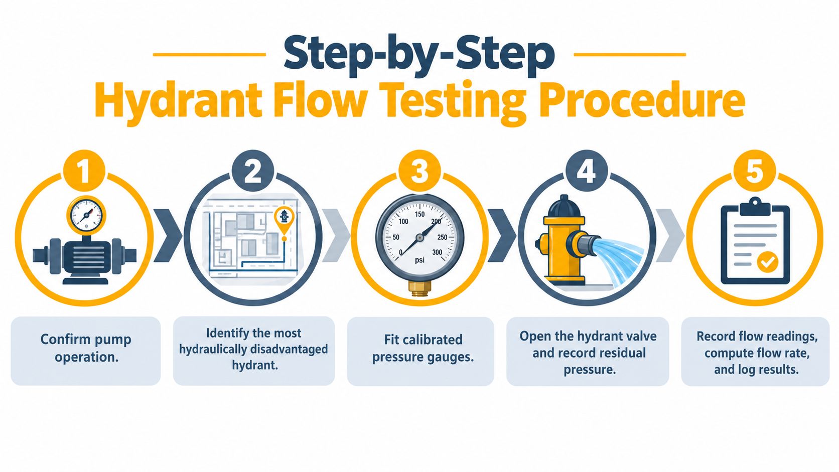
5. Record and interpret the result
Record static pressure, flowing pressure, measured flow, the test hydrant, gauge identification, pump status and any unusual condition. The result must be assessed against the design criteria, including the Queensland benchmark of 10 L/s at 200 kPa for the relevant building and system arrangement.
A certificate that says “tested satisfactory” without identifying the test point and readings gives the owner limited evidence. Good records let the next technician distinguish a gradual change from a one-off reading and help the water authority understand what happened if the private system checks out.
For a practical visual reference, see this fire hydrant flow testing guide. The following video can also help non-technical stakeholders understand the test sequence before a service visit.
When the Test Fails and It Is Not Your Fault
The difficult result is a hydrant that fails to reach its design performance even though the private installation appears sound. The valves operate, the booster starts, the ring main holds static pressure and there are no obvious leaks. Yet the critical hydrant still records inadequate flow or residual pressure.
Queensland's commissioning and maintenance guidance gives this situation a clear escalation path. If pressure or flow doesn't meet the design criteria and no on-site fault is found, the tester should contact the relevant water service provider because the limitation may sit in the network rather than the building system. The Queensland Form 72 hydrant testing and maintenance guidance is particularly useful because it connects the test result with the cross-boundary response that many general guides leave out.
| Symptom | Likely Site Fault | Likely Network or Supply Issue |
|---|---|---|
| Low static pressure | Closed isolation valve, faulty gauge, tank level issue or supply valve restriction | Reduced street pressure, network configuration or utility-side restriction |
| Pressure collapses during flow | Undersized or damaged private pipework, blocked strainer, faulty pump or restricted valve | Insufficient available mains capacity under demand |
| Good result at one outlet, poor result at the critical outlet | Local branch restriction, incorrect isolation or hydraulic design issue | Network limitation affecting the site supply at the test condition |
| Pump runs but output remains low | Pump fault, control issue, suction restriction or inadequate water source | Incoming supply cannot support the pump arrangement |
| Results vary between visits | Different test setup, instrument issue or inconsistent valve operation | Variable street supply or changing network demand |
Start with the private side. Confirm the correct valve positions, inspect strainers and gauges, verify pump operation, check the test facility and compare the current readings with earlier certificates. A competent technician should document each check rather than record “no fault found”.
If the site evidence remains consistent and the limitation is at the boundary, send the water service provider a complete pack. Include the test date, location, static and residual readings, flow measurement, system type, pump status, site address and relevant design information. In South East Queensland, street hydrant flow and pressure documentation may also form part of building certification, so the failure can affect both maintenance decisions and approval records.
Maintenance, Inspections, and AS 1851 Routines
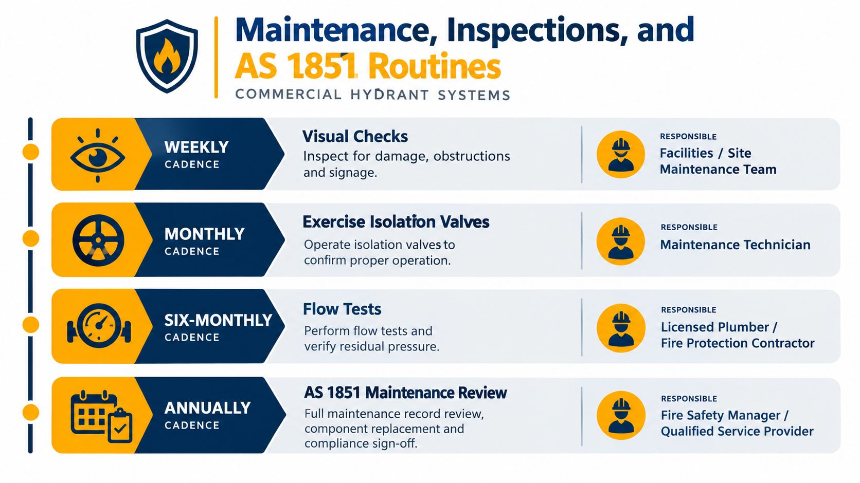
A hydrant system can comply at handover and deteriorate later. Landscaping can cover a pit, a tenant can store goods in front of a cabinet, a valve can seize, signage can fade and a pump room can become difficult to access. AS 1851 provides the framework for ongoing inspection, testing and maintenance, while the maintenance work must continue to reflect the original AS 2419.1 design assumptions.
The exact service program should be confirmed for the building, its approval conditions and the responsible maintenance organisation. A practical Queensland commercial schedule separates routine checks so defects are found before the formal flow test.
Weekly site checks
Walk the hydrant route and look for damage, obstruction, locked access, missing caps, blocked cabinets, deteriorated signage and unsafe discharge areas. These checks are quick, but they catch the site-management issues that a specialist may only see after arriving for a scheduled test.
Monthly operational checks
Exercise relevant isolation valves under the approved procedure and confirm that valve identification remains accurate. Don't operate a valve casually if its position affects another protected area. The person conducting the check should understand the system arrangement and restore every valve to its required normal position.
Six-monthly flow verification
Perform the flow test at the most hydraulically disadvantaged hydrant and record the residual pressure under the specified flow condition. Queensland's maintenance procedure specifically links the test to a flow measuring device and residual pressure reading, so a visual inspection alone isn't a substitute for performance evidence.
Annual record review
Review the full maintenance file, defect closures, component condition, test equipment records, drawings, booster documentation and site access. Replace damaged fittings and update the hydrant block plan after repairs or layout changes. The commercial fire protection maintenance service information describes the type of scheduled coordination facility managers often need across multiple fire safety assets.
The person signing a record should be appropriately competent and authorised for the work being certified. Queensland forms and procedures tie hydrant commissioning and maintenance to the Building Act 1975 and Queensland Development Code Mandatory Part 6.1, so facility managers should retain the completed forms and supporting evidence rather than relying on an invoice alone.
Missed periodic flow tests create an obvious audit gap, but the underlying problem is larger. Without regular testing, an owner may not know whether a change in pressure comes from a private fault, a pump issue or the public network. Routine records preserve that comparison.
Putting It All Together for Compliance
Before an audit, assemble the system evidence as one connected file. The goal isn't to produce a stack of unrelated certificates. It's to show that the installed system matches its design, that the critical outlet has been tested, that defects were managed and that the owner knows what to do when the water authority controls the limiting condition.
Pre-audit checklist
- Design basis: Keep the approved hydraulic design, current drawings and relevant AS 2419.1 information available.
- Site layout: Confirm hydrant access, booster access, signage, vehicle approach routes and clear valve identification.
- Water supply: Record whether the system is pumped or un-pumped and retain available water authority information.
- Test facility: Check that test inlets, drains and discharge routes can support the required flow without creating an unsafe condition.
- Performance results: Retain commissioning data and periodic certificates identifying the test hydrant, flow, pressure and instruments.
- Booster evidence: Include pump operation, controls, alarms, tank or mains supply details and any defects or repairs.
- Maintenance history: Keep routine inspections, valve checks, flow tests, repair records and updated block plans together.
- Network correspondence: Save water service provider communication where results indicate a possible street supply limitation.
The performance target for the applicable Queensland commercial arrangement remains 10 L/s at 200 kPa at the relevant test point, with the most hydraulically disadvantaged hydrant governing the assessment. That target should be read alongside the approved design and applicable building requirements, not isolated from them.
When a result fails, use a controlled sequence. First, verify the instrument and test setup. Next, check valve positions, strainers, pump operation, tank or mains conditions, branch restrictions and drainage arrangements. Then repeat the test where appropriate under controlled conditions. If the private system has no identified fault, provide the documented result to the water service provider and ask for a network investigation.
A hydraulic consultant should be engaged when the design basis is missing, the building has complex pressure zones or towers, proposed alterations affect hydraulic demand, or repeated results cannot be reconciled with the existing drawings. A consultant can also help determine whether a pump, tank, pipework alteration or revised test facility is technically justified.
The most reliable commercial fire hydrant systems are designed for the entire lifecycle. They can be accessed, flowed, drained, isolated, repaired and documented without guesswork. That's the standard facility managers should apply before approving a new installation, accepting a handover or closing an audit finding.
Celtic Fire & Security provides commercial fire hydrant inspection and controlled flow testing for un-pumped systems, with testing and compliance documentation for ongoing records. Visit Celtic Fire & Security to discuss hydrant testing, maintenance and broader fire protection support across North Brisbane, Moreton Bay, the Sunshine Coast, Somerset and Ipswich.
No responses yet